 |
||||||||||||||
|
Wiring IssuesSockets
The socket on a telephone is always a 4-way RJ-11. In the UK, the line from the telephone exchange is terminated on pins 2 and 5, of the 6-way socket. In Ireland, the line from the telephone exchange is terminated on pins 3 and 4, which are the centre contacts of the RJ11 socket. Pins 3, 5 and 4 are looped to pins 1, 2 and 6 respectively via breakable jumpers. These jumpers allow the socket to be converted to a full 6-way socket. One or more secondary sockets can be terminated on pins 1, 2 and 6. Incoming ringing current (75V AC) is de-coupled by the a capacitor in the master socket to the R terminal. When this socket was introduced, most telephones used loop pulse dialling, which meant that other telephones wired in parallel would 'tingle' as the digits were dialled. Older telephones use the third wire for the bell, however, newer telephones use only two wires, internally de-coupling the ringing. If all telephones use two wires and DTMF dialling, the tingling problem no longer exists, eliminating the need for the third wire between sockets.
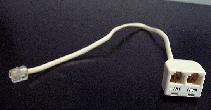
Figure 2. Figure 2 shows a master socket and the first secondary socket. The bell circuit of a three wire telephone is connected to L2 and R. If the secondary socket is incorrectly wired, with L1 and L2 being swapped, the bell circuit would now be connected to L1 and R of the master socket, which are effectively the same. The transmission and reception circuits of the telephone would still operate, as they would remain connected across L1 and L2. This becomes important when connecting a telephone designed for the UK market to the Irish telephone system. The UK system uses the same master / secondary arrangement, but, L1 and L2 are the outside pair of the UK 4-way plug, while R is one wire of the inside pair. Simply replacing the 4-way BT plug with an RJ-11 plug doesn't mean that the telephone will work. It is necessary to swap the inside pair with the outside pair. To complicate things further, the R wire from the socket must be connected to the correct pins of the telephone. In short, the golden rule is to replace the BT plug on a BT plug to RJ-11 cable with an RJ-11 plug, swapping the inside pair with the outside pair, and turning the plug upside-down. One complication can arise, especially with newer modems. Many modems have only one RJ-11 socket, due to reduced manufacturing costs, and in many cases, the modem is intended for use as the only device to be connected to the telephone socket.
Test Page | Test Information | Leslie
Long's Homepage | Email |
|||||||||||||
 The master socket used
in Ireland accommodates a 6 way RJ11 plug. Most cables
used to connect the telephone and the wall socket only
use 4 pins (2 through to 5). Similarily, the socket used
in the UK is a 6 way socket, but is physically different,
and also wired differently.
The master socket used
in Ireland accommodates a 6 way RJ11 plug. Most cables
used to connect the telephone and the wall socket only
use 4 pins (2 through to 5). Similarily, the socket used
in the UK is a 6 way socket, but is physically different,
and also wired differently.