|
|
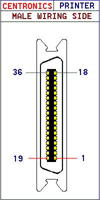
| Centronics - Parallel Interface |
| |
| The Centronics Parallel interface has become accepted as the standard
connector used between a PC and a Printer.The interface carries an 8 bit byte
in parallel which is clocked in to the printer using the STROBE pulse signal
supplied by the Computer (PC). |
| |
| Pins 12,13,14,15,18 , 31,32,34,35 and 36 can be different from manufacturer
to manufacturer but the following table should be a general idea of their use
as well! |
| |
| Signal Pin Number |
Return Pin Number |
Signal Name |
PC ------- Printer
Direction |
Description |
| 1 |
19 |
STROBE |
Printer Input |
Pulse (negative
going) enables reading of data from data lines |
| 2 |
20 |
Data bit 1 |
Printer Input |
1st to
8th bits of parallel data. Each signal is HIGH for logical 1 and LOW for 0
.
|
| 3 |
21 |
Data bit 2 |
Printer Input |
| 4 |
22 |
Data bit 3 |
Printer Input |
| 5 |
23 |
Data bit 4 |
Printer Input |
| 6 |
24 |
Data bit 5 |
Printer Input |
| 7 |
25 |
Data bit 6 |
Printer Input |
| 8 |
26 |
Data bit 7 |
Printer Input |
| 9 |
27 |
Data bit 8 |
Printer Input |
| 10 |
28 |
ACKNLG |
Printer
Output |
LOW indicates that
Data has been received and the printer is ready for more data. |
| 11 |
29 |
BUSY |
Printer
Output |
HIGH indicates that
the printer cannot receive data. |
| 12 |
|
|
|
|
| 13 |
|
|
|
|
| 14 |
|
|
|
|
| 15 |
|
|
|
|
| 16 |
|
Logic Ground |
Ground |
Ground for
STROBE,ACKNLG and BUSY signals |
| 17 |
|
Chassis
Ground |
Shield |
Cable Shield |
| 18 |
|
|
|
|
| 31 |
|
|
|
|
| 32 |
|
|
|
|
| 34 |
|
|
|
|
| 35 |
|
|
|
|
| 36 |
|
|
|
|
|
| |
|