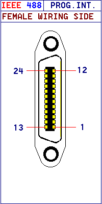
IEEE 488 Programmable Interface
|
This interface is for Programmable Instrumentation using a Data
Bus between instruments to transfer data to and from the various instruments
connected.
The interface uses voltage levels of +5V DC for logical 0 (False) and pulls
this to ground for logic 1 (True) . Devices on the bus are called GPIB Devices
(General Purpose Interface Bus !! I Think!!) and can be one of three types
- Talker : a device configured to allow
it to put data on the bus , transmitting data to one or more other
devices. There may be only one talker active any one time.
- Listener : this accepts data from the bus using
handshaking signals . There may be more than 1 listener active at any one time
.
- Controller : The controller is the only device on the bus
capable of asserting the ATN line which tells all the devices on the bus to get
ready to receive commands. There is only one controller active at a time in the
system . When two or more controllers are connected to the bus then control
must be passed from one to the other.
|
 |
| |
Bus structure
|
| The GPIB consists of 16 active lines divided into three groups
, Control , Data and Handshake lines. |
| |
| DATA LINES |
| The data bus D101 to D108 is used to transmit data bytes ,
control bytes and device addresses in a parallel byte, The data can be binary
or ASCII characters. |
| |
| CONTROL LINES |
The control lines define how the data on the D101 -D108 is
to be interpreted.
IFC (Interface Clear)
- Used by Controller to put all the deices in a quiet state .
SRQ (Service Request)
- Asserted by a device when it requires a service sequence.
REN ( Remote Enable)
- When REN is asserted by the Controller the listener will ignore its front
panel controls.
EOI (End or Identify)
This line has two functions :
- END : Asserted by a talker to indicate the
end of a multi-byte message.
- Identify : Asserted by controller with the ATN line when conducting
a parallel poll.
|
| |
| HANDSHAKE LINES |
| These are 3 signals used to exchange data across the GPIB. |
| DAV |
- Data Valid : Asserted by controller to indicate it has put a Control byte
on the bus.
|
| NRFD |
- Not Ready For Data : Active listener asserts this line to prevent data
being put on the bus until it is ready for it.
|
| NDAC |
- No Data Accepted : An active listener asserts this line to indicate
it has not yet accepted the last byte on the bus.
|
| |


